↑top
Touchscreen UI
Overview
In this section we will present the web application made for the 7’’ touchscreen monitor for Raspberry Pi. Its main functionality is to manage routes for ConveyorBot. When the touchscreen application is started, first the “Loading screen” is shown. This screen automatically switches to “Control panel screen”, after the robot is initialized. You should avoid using the robot while it is initializing. On the top of all screens, there is a menu bar, which offers functionalities like rebooting the robot, monitoring battery percentage, navigating to “Control panel screen”, etc. On the top right corner of the “Control panel screen”, there is a map icon which leads to “Route settings screen”. On that screen, the routes can be set up.
Touchscreen UI adds an additional three features to the basic ConveyorBot usability:
- In order for the ConveyorBot to start moving on the route, START button on the touchscreen should be pressed
- During the drive, the robot can be stopped by pressing the STOP button (START should be pressed to continue)
- ConveyorBot will stop on STOP marker and wait for the user to press CONTINUE
Control panel screen
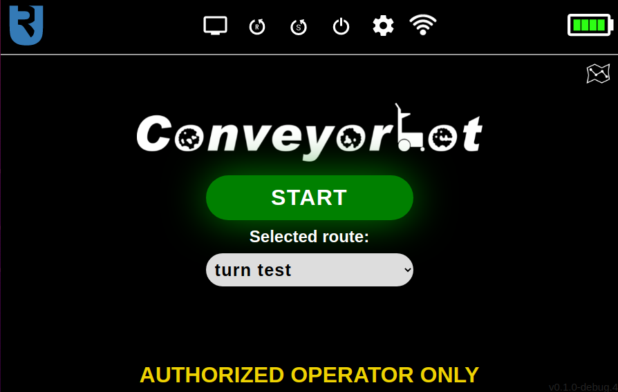
The most noticeable part of the “Control panel screen” is the big green “Start/Stop button”, with “START” written on it. After pressing it, it changes its color to red and its text to “STOP”. It is used for the robot to start or stop following the markers of the currently selected route. When the robot finishes the route by stopping on a STOP marker, this button changes its color to blue and its text to “CONTINUE”. Now, when pressing this button, the robot will start following the route again from its beginning.
The route can be easily selected in the dropdown menu, which is located below the “Start/Stop button”. To edit, create or delete a route, the gear icon in the top right corner can be pressed, which leads to the “Settings screen”. If you want to reset the route (to start the route from the beginning), you should select another route and then the desired route again (currently there is no “reset route” button).
The Control panel screen with route “turn test” selected is shown on the image below.
Menu bar
The menu bar is present on the top of all screens. On its left side, there is a Ubiquity Robotics’ logo, which is actually a button that always leads to the “Control panel screen”. On the right side of the menu bar, there is a battery level indicator. When the battery goes under 40%, a low battery popup will be shown. When this happens, you should stop using the robot and start charging it. In the middle, there are several buttons, each having its own functionality. The first one (from left to right), shaped as a computer monitor, leads to the “Debug screen”, on which the user can monitor the camera’s image stream and detected markers or move the robot with the software joystick. The second button, shaped as a letter “R” in a circular arrow, prompts the user to reboot the robot. The third button, shaped as the letter “S” in a circular arrow, prompts the user to reboot the robot’s software. This is useful, because it functions in a similar way as rebooting the robot, but is faster than it. The fourth button, shaped as an on/off symbol, prompts the user to turn off the robot. The fifth button, shaped as a sprocket, leads the user to the “Debug settings” screen. On this screen there are additional settings for updating and recording ROS’ topics into a “bag file”. This is used for debugging purposes. The sixth button is a WiFi state indicator. If the robot is connected to the WiFi, this button has a regular WiFi icon shape, indicating the WiFi strength. If the WiFi is disconnected, it has the same shape, but with a cross symbol drawn over it. If the WiFi is in the hotspot mode, it has a shape of two regular WiFi icons rotated by 90° to left and right. Pressing on this icon displays the WiFi info, which is the IP address, SSID and the hostname. Here you can also connect to a new WiFi access point by entering the SSID and password into appropriate fields and clicking on “Connect to the new WiFi” button.
Route settings screen
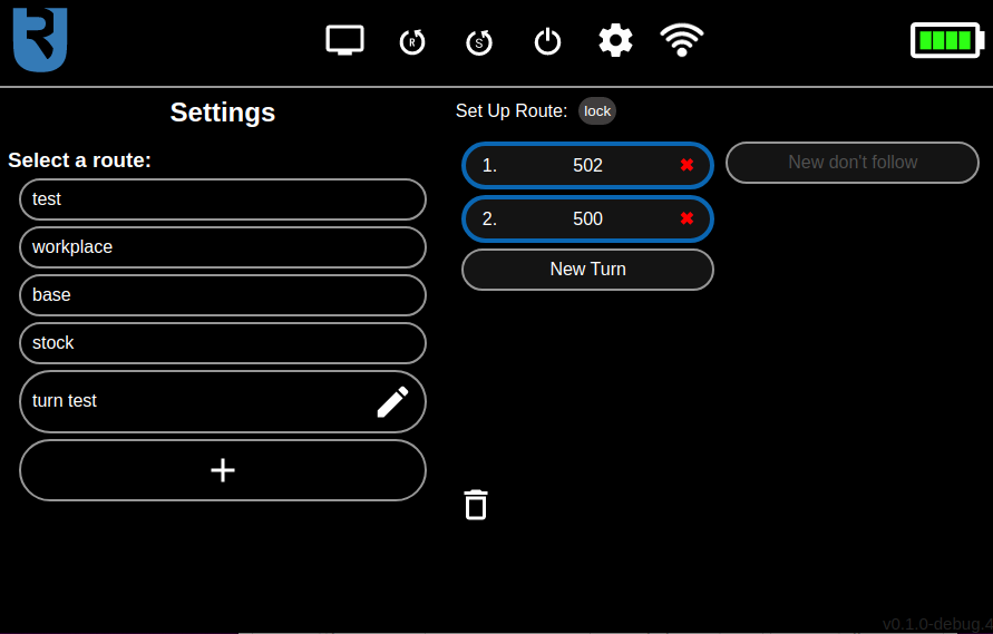
On the left side of this screen, there is a route selection part. To add a new route, the “+” shaped button below all routes can be pressed. When clicking on any of the routes displayed here, the route editor will be displayed on the right side of the screen, where you can edit the selected route.
The route editor has two columns. In the left one, the markers to follow can be specified and on the right part, the markers to ignore can be specified. The specified markers can also be rearranged by dragging and dropping them. The drag and drop functionality can be disabled, so that the list of markers can be scrolled up and down, without accidentally rearranging the markers. This can be done by clicking on the “lock/unlock” button above the left column. The function of “markers to follow” and “markers to ignore” and instructions on how to correctly set up a route will be described in the next section.
To delete the route, which is currently being edited, click on the button with the bin icon on the bottom of the screen.
The settings screen is shown on the image below.
Route management
The route management functionality allows ConveyorBot robot to navigate itself in a more advanced manner. If you press the route settings button on the Control Panel screen, you’ll see the main route management page. This was described already in the previous section of this page.
Now we will tell you how to properly set up a route. An analogy for how the route setup works is the way somebody navigates you while driving a car. The navigator only tells you where you have to turn in the crossroads - he doesn’t tell you that you have to go straight on a road which is itself straight (and has no other ways to turn), or to stop where there is already a stop sign. So, to set up a route on which the robot will drive, you have to specify only the sequence of TURN markers in the crossroads of the route. Actually, all other TURN markers (the ones which are not specified in the route plan) are ignored by default. You don’t have to specify GO, STOP or BIDIR markers (but you have to do this in a special case, specified later in this section). To get more information about all types of markers, navigate to the Marker Types and Placing Markers in the Desired Location section.
To specify the order of turns in crossroads, put the numbers of TURN markers, which mark the appropriate turns, into the left column of the route editor in the correct order.
In the left column of route editor, you also need to specify all STOP markers on which you want the robot to stop. If you don’t do that, the robot will ignore STOP markers by default.
If you want to completely ignore a marker, put it into the right (“Don’t follow”) column. An example of where this could be useful is if there is another marker setup, independent from the current marker setup close by. In that case you need to put the markers from the other setup you wish to ignore into the right column.
When creating the route, you have to be careful that the first marker is close enough for the robot to detect it, otherwise the robot won’t start. You can see if the first marker is detected in the Debug screen. It should have a green outline on the camera image.
A special case, where you have to specify GO, STOP and BIDIR markers in the route is, if there are two markers from the same crossroads in the route one after another. This would happen, for example, when the route goes from a crossroad to the STOP marker, which is directed back to the same crossroad. In this case, this STOP marker also has to be specified in the marker list. In general, at least one marker on a part of the route which goes out of the crossroad and then back to the same crossroad has to be specified. This is a current issue and it will be resolved in further updates.
Note that after changing the route in any way, it will be resent to the robot automatically and started from beginning, so you should move the robot to the start of the route after doing that.
Remainder route
(Be aware that this is an experimental feature and might not work as expected in all cases. It will also probably be removed in the future.)
When performing an action which would override an unfinished route, a remainder of that route is saved as a route with name “<remainder>”. This is useful, because if the user accidentally selects a different route or exits the software, he/she won’t have to manually drive the robot to the end/start of the route, but the robot will just continue where it left by selecting the “<remainder>” route.
Depending on where the robot was interrupted, the remainder might be one marker too long - the first marker of the remainder route might not be visible by the robot anymore. In that case, the user should delete the first marker by manually editing the remainder route.