Marker types and placing markers in the desired location
The ConveyorBot navigagtes using floor stickers called fiducials. There are several types of fiducials:
| Marker type | Image |
|---|---|
| Go marker has a single arrow which points to the direction where the ConveyorBot will drive. | 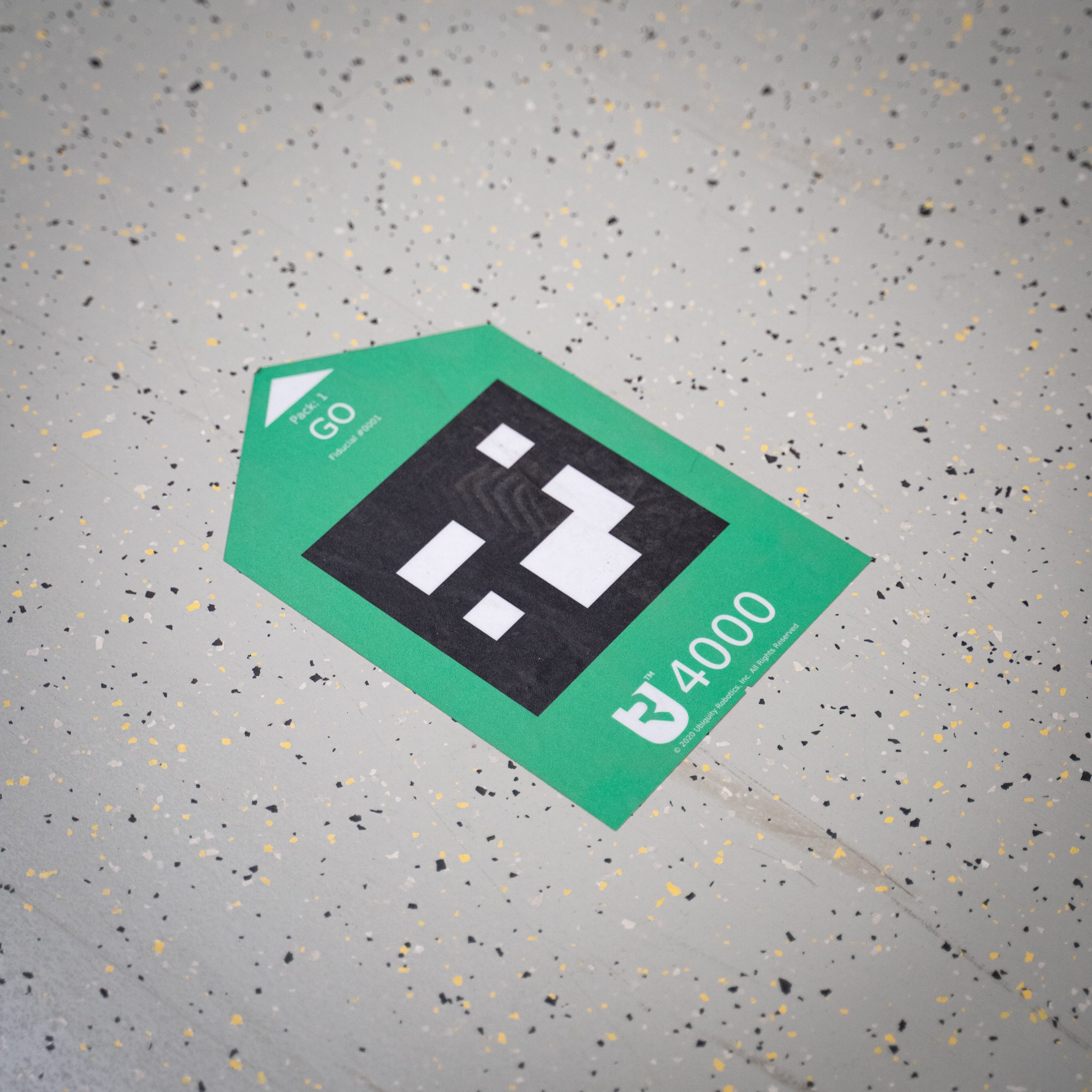 |
| Stop marker will casue ConveyorBot to stop at that spot. After the ConveyorBot moves on top of the Stop marker it rotates in a direction of a marker arrow. While ConveyorBot waits on a stop marker the user can load or unload the packages. The robot will resume following markers when user presses the CONTINUE button on the touchscreen of the ConveyorBot. | 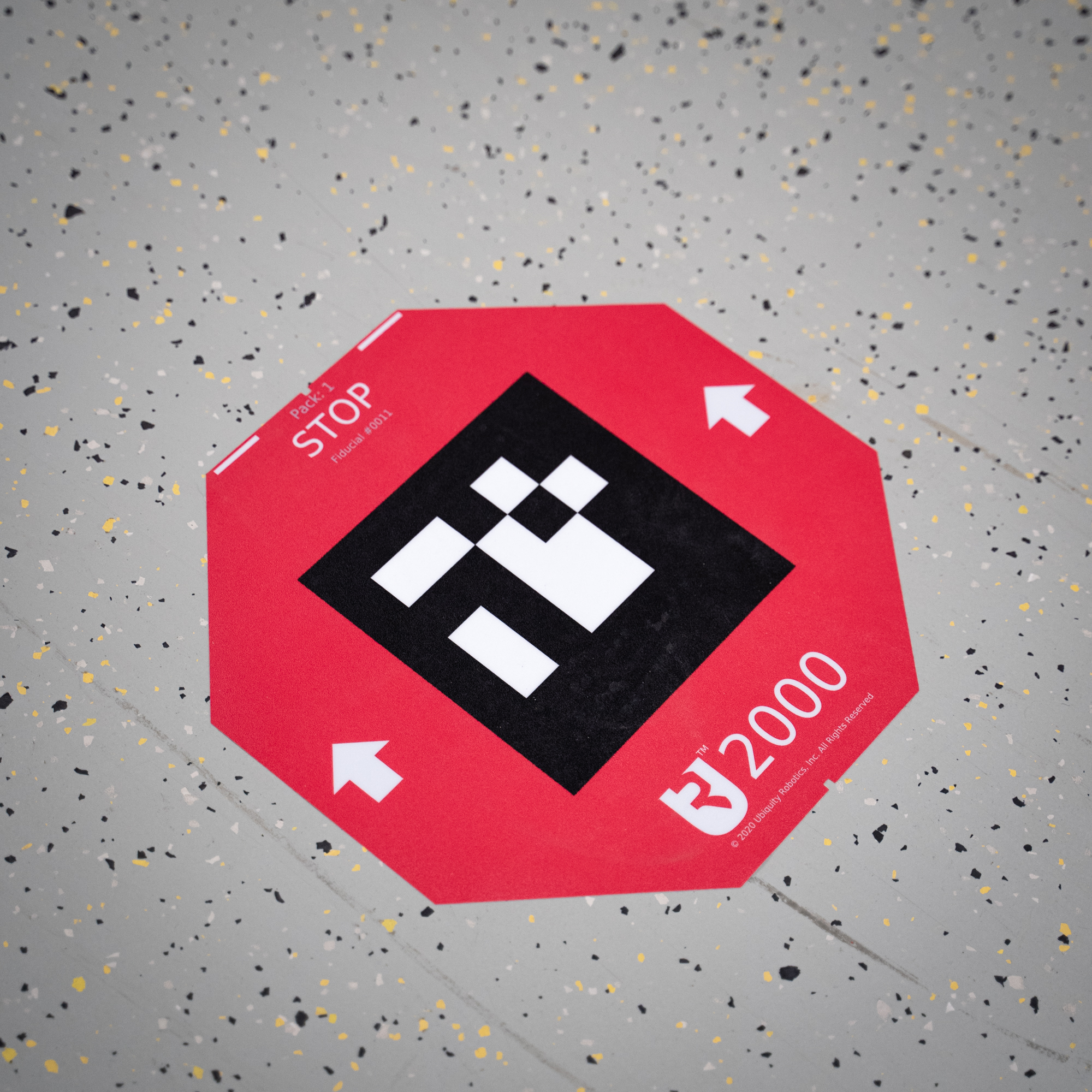 |
| Turn marker is made for creating crossroads. When the robot comes to a crossroad where it will see several markers it will follow only the one that its programmed to. You can program routes in the robot that consist of the sequence of turn markers to follow and the robot will follow those in turn to reach the desired location. | 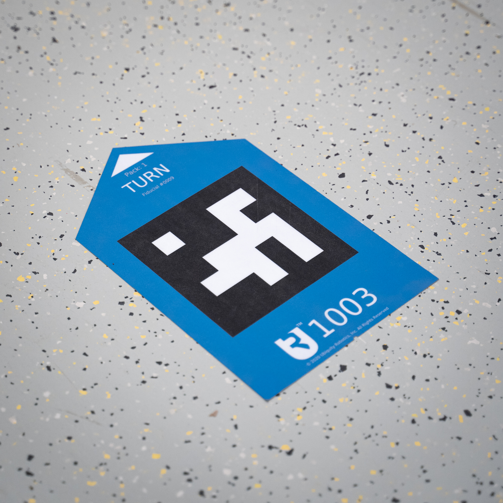 |
| Bidirectional marker is the only marker with 2 arrows in it. ConveyorBot drives allong the arrow that requires less robot rotation. Bidirectional marker is good for two-way routes where ConveyorBot requires to move in both directions for example narrow aisles where there is not enough space for both a forward and return path. | 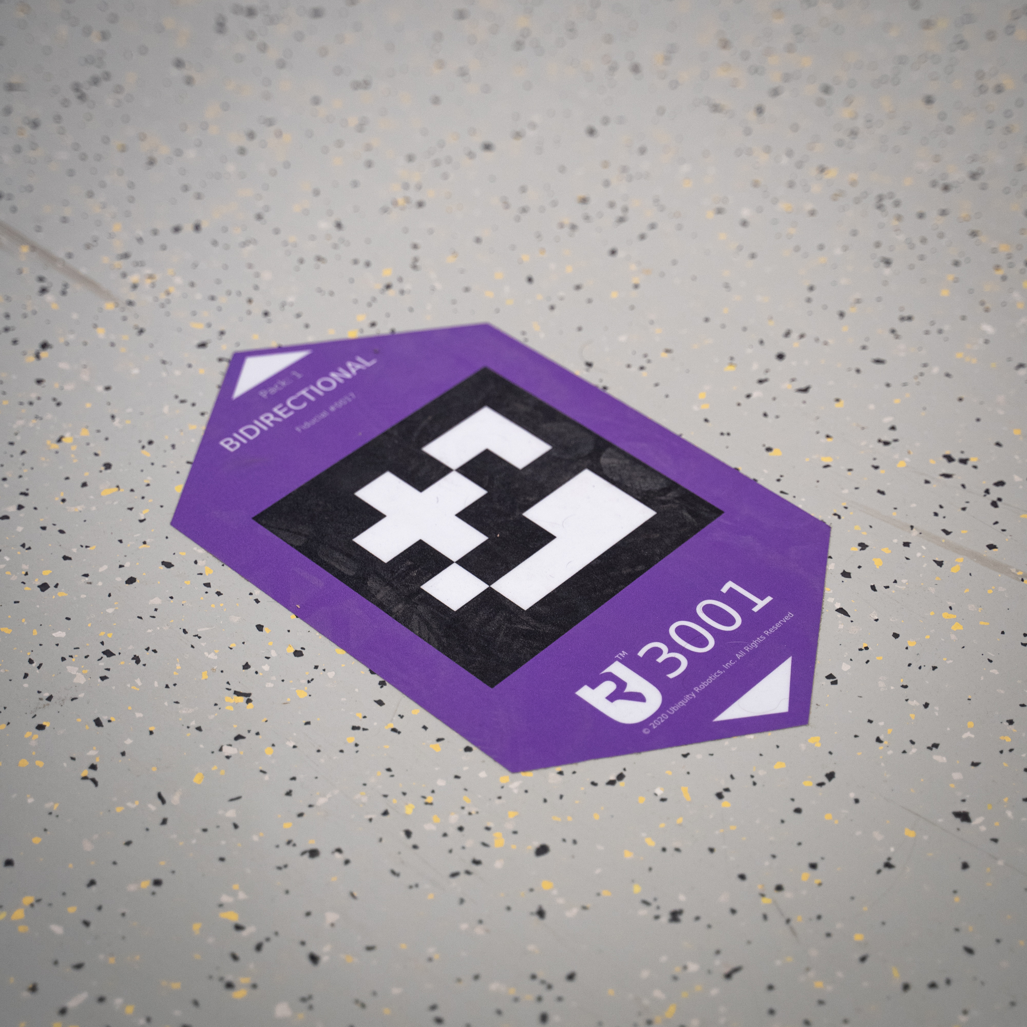 |
ConveyorBot is enabled to be used either with STag or ArUco markers. The analogy of marker types is the same for both. The recommended and default type of markers is STag.
Each marker has a unique id, which is written on it. This way marker types are correctly distinguished which correspond to the correct ConveyorBot manevers.
How to place the markers
The most important things to remember before setting up the route of markers are:
- Each marker should point in the direction of the next one
- TURN markers should be used to change driving direction (At crossroads - multiple markers at one position pointing in different directions)
- BIDIRECTIONAL markers should be used for two-way routes, where robot can drive in both directions and not for changing the driving direction. In other words, robot should never come sideways to the BIDIRECTIONAL marker, since it may turn in the wrong direction as intended.
- If you expect to have more than one robot on a route, you should have a seperate outbound and return path otherwise robots may meet head to head, which will cause both robots to stop. BIDIRECTIONAL markers should only be used on branches where you expect only one robot to be present in that branch at a time
- GO marker should be used for one-way routes, where robot can drive only in one direction
- Before sticking markers to the ground using their strong adhesive back side, it is recommended to stick them to the ground using some tape, so that you can test if your route setup is correct. Be careful that you don’t cover the inner black part of the marker with the tape. After you’ve made sure the route is setup correctly, you can stick the markers by removing their back side. Stick the markers onto clean floor.
Markers are sticky stickers that can be peeled off and placed on another floor location. But it is not recommended to peel it off too many times as the glue on the marker can dry out.
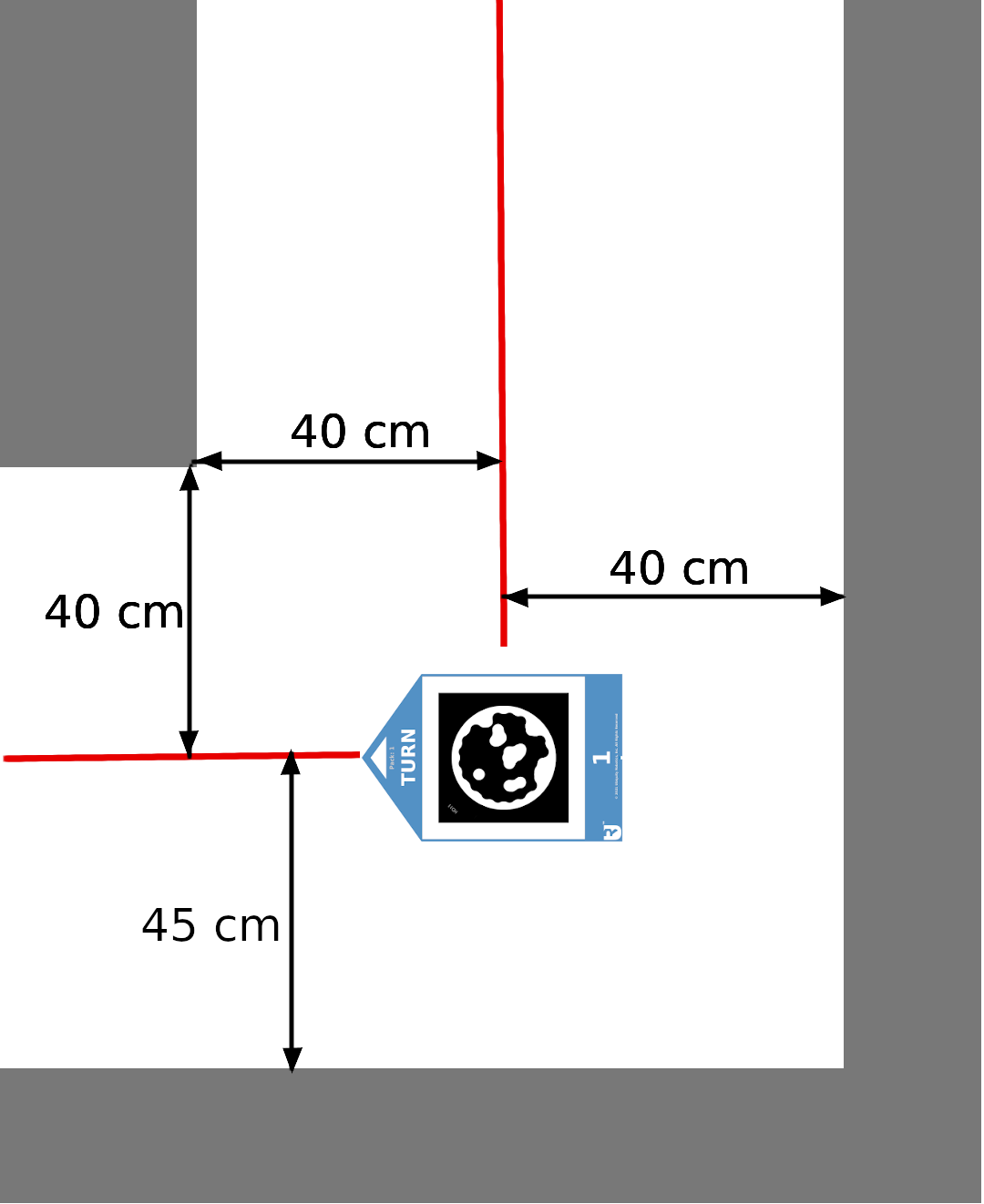
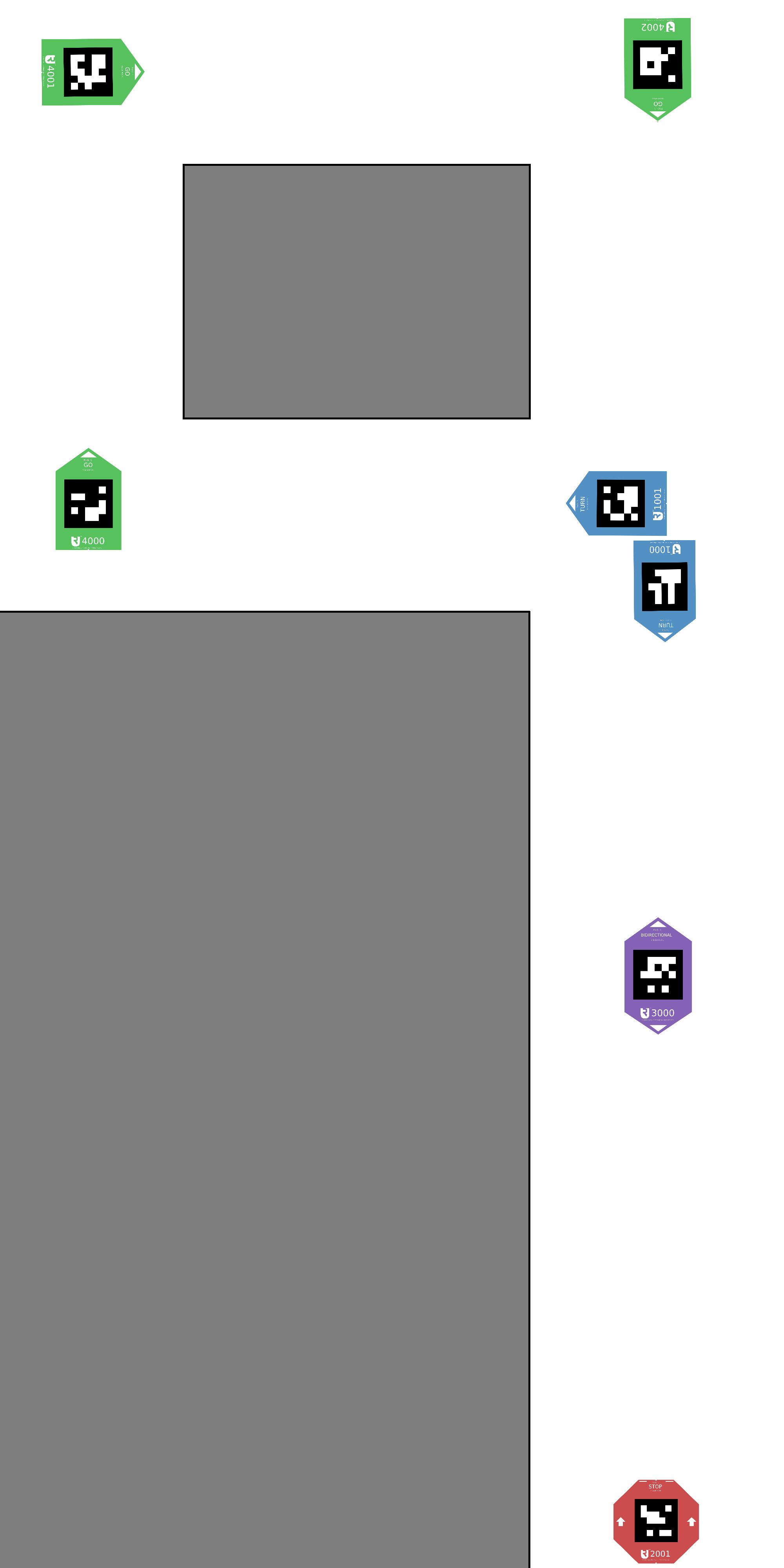
An example of a simple marker layout is shown in the figure below.
Ignored opposite markers
By default, the GO markers which are rotated in the opposite direction as the robot is driving are ignored. This is so that the outbound path and return paths work correctly when inbound and outbound paths are close together (refer to the next section). Otherwise, if the robot is driving on the inbound path, it might detect and follow the opposing markers from the outbound path.
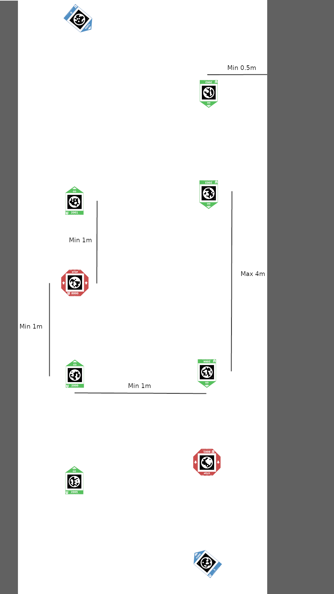
Circuit route
If you want multiple robots to drive on the same marker setup, you should arrange the markers in a so-called “Circuit route”, so that the robots won’t collide into each other. This type of marker setup is recommended even if you have only one robot, because you never know when you will add another robot to your fleet. We divide circuit route into an inbound and an outbound path. Inbound serves as the path for robots to drive to the goal and the outbound is the path which is used for the robots to return back to the starting point. The inbound and outbound paths should be at a little more (about 20 cm more) than 1 robot width apart, so that the robots can pass each other without collision. If you have space, its convienient to place the routes 1 meter apart. On both ends of the path, markers should be arranged in a specific way, shown in the image bellow. When setting up a route, the measurements from the image bellow need to be considered. If you want to include a STOP marker into the Circuit route, the best way of placing it is one meter behind the GO marker. GO markers must be max 4-5 meters apart regardless of where you put the STOP markers, because the STOP markers are ignored in the case if you don’t want the robot to stop on them. As seen from the image, on each end of the Circuit route, there is a TURN marker, which you need to include into the route on the touchscreen. This can’t be a GO marker, because it would be ignored as it is turned in opposite direction as the robot’s driving direction.
Branches from main circuit route
You can also do “branches” from the main circular route similarly as shown on the image bellow.
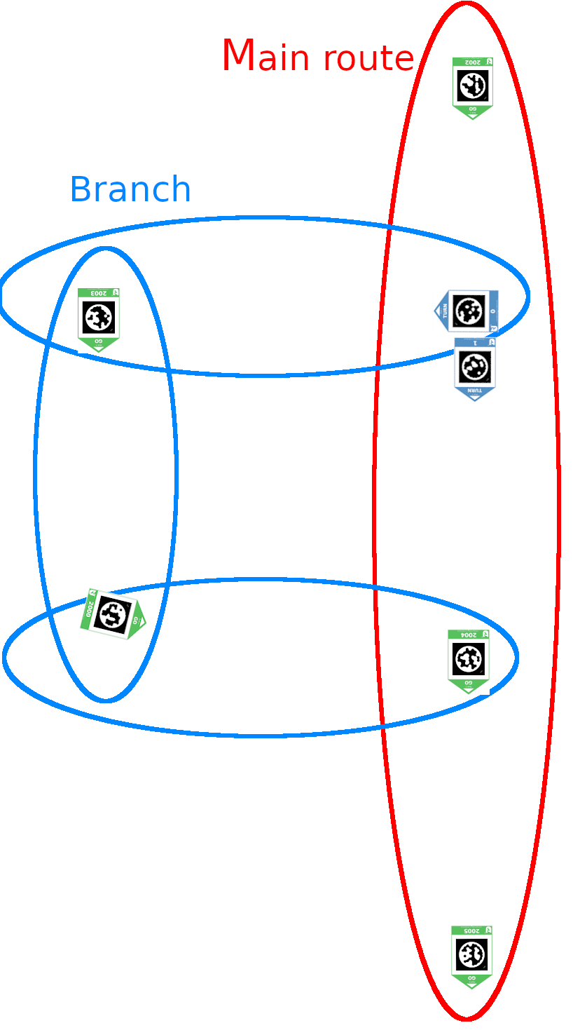
As you can see, there is a possibility that two robots would collide into each other on the marker where the branch merges back into the main route. This is handeled in a way that the robot comming from the branch always “looks” to the left with LIDAR in order to see if there is another robot approaching from the main route. If this is the case, the robot approaching from the branch will stop and wait for the robot on the main route to pass.
But this introduces a problem. The robots always look to the left when turning right on a marker in order to detect a potential robot on the main route. This means that if the robot is just turning right (and it is not going back to the main route), ideally there should also be about two meters of clearance on the left side of the robot so that the wall or any other obstacle is not detected as the robot approaching from the main route. So, if the robot is driving in a hallway which is turning right, you should put the inbound path as close to the right wall as needed so that there is still 2 meters of clearance on the left side of the robot. Or, if that’s not possible, you should disable t collision detection for each individual marker, that makes the robot turn right, on which you don’t want the robot to stop because of the obstacle on the left. This can be done on the touchscreen’s route settings screen. By clicking on any marker in the route, a popup will open where you can check the “Disable T collision check” checkbox. Bear in mind that to rejoin the main route at the point where the main route makes a 90 degree turn will create problems with this collision avoidance. Please rejoin the main route a few cm earlier than where the main route takes a 90 degree turn.
Narrow hallway limitations
There are some minimum distances from the route to walls which are presented on the image bellow.