Fiducial-Based Localization
↑top
This document discusses running our fiducial based navigation software on a Ubiquity Robotics robot base, using the supported Raspberry Pi camera. It also assumes that you have a workstation with ROS installed, which is connected to a network in common with the robot. You will need a printer, too.
This description assumes that all fiducials are on the ceiling. Actually, this is not required if our software is used in the arbitrary mode but we feel it is easier to visualize and learn about fiducial navigation using the ceiling mode.
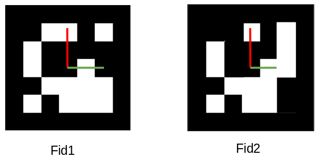
We use Aruco Style Fiducial markers
We use the Aruco style Fiducial Markers and try to so far use the ones where the ‘checkerboard’ patern is a 5x5 grid. The default library we generally stick to is called DICT_5X5_1000 so if you print some markers shown below they will by default come for that Aruco library.
Basic Concept
The Ubiquity Robotics localization system uses a number of fiducial markers of known size (illustrated below). Detection of the markers is done by using the robot’s camera. The characteristics of the images of the fiducial markers enable the robot to compute its location.
Detection And Processing Basics
In our launch files we will have a node to detect Aruco fiducials from the camera images. The output of this aruco_detect node goes to two topics where one topic give the verticies of each detected fiducial and another topic publishes the transforms of each fiducial relative to the camera itself.
You may want to take a look at the Aruco Detect Wiki if you are curious about detection of fiducials for other nodes you may want to form to do other things besides navigation.
We have other nodes that subscribe to the aruco_detect topics to then do the math to sort out where each fiducial is relative to the robot itself using 3D math and form the map or use the map to navigate.
Print Some Fiducials
A PDF file containing a range of fiducial markers can be generated on your workstation with a command such as:
rosrun aruco_detect create_markers.py 100 112 fiducials.pdf
The 100 and 112 specify the starting and ending numerical IDs of the markers. It is not important what these are (we recommend starting at 100), but it is important that each marker has a unique ID. Print the PDF file to produce the fiducials.
We use 140mm fiducial patterns that must be printed to be 140mm. Our launch files can be customized to use another size for fiducials but we recommend use of 140mm.
Check the Fiducials
The fiducials must be printed accurately. The image must be 14 cm by 14 cm, to within half a millimeter. Depending on the printer settings, these dimensions may be off. For instance, the printer may be trying to fill the page. Measure with a good rule, and change the settings if necessary.
Mount the fiducials
Affix the fiducials (in any order) to the ceiling where they will be viewed best by the robot’s camera. They need to be at a sufficient spacing so that more than two are visible at a time for this example where we are using flat floor navigation. The RaspiCam version 2.1 camera we ship has about a 62 x 49 degree field of view so you will have best results for a standard 8 foot tall ceiling if you space the fiducials about a meter apart. It is also best to try to avoid placing fiducials right next to or on the covers of overhead lights. The fiducials do not have to be in an ordered arrangement and in fact are best if spaced in a non regular arrangement. Some of our software performs best if you avoid having a very fixed grid of fiducials so perhaps consider every other row is staggered by a half spacing of the grid if you feel you must order them to look “neat”.
Setup The RaspiCam for Upward Facing Navigation
If your camera points straight up instead of forward, the file /etc/ubiquity/robot.yaml must be edited to change the default (which is “forward”). To do this, add the following 2 lines to /etc/ubiquity/robot.yaml:
raspicam:
    position: 'upward'
Your mapping will give you the best results if the camera on your Magni robot that is facing upward is precisely pointing straight up. Even an error in 1 degree will show up as several centimeter location error for a robot that is pointing one way vs when the robot points the opposite direction (You can work out the trigonometry if you like)
We are working on a calibration we hope to introduce in the near future but until then we suggest you use a 1” round bubble level and place it on the 4 screws that hold the RaspiCam (on a powered down Magni with no RaspiCam screwed into the screws). Then after the RaspiCam is screwed back in with the Magni on a level floor, gently use pliers to get the bubble level to be centered by small bends to the RaspiCam bracket on the Magni. Some RaspiCam units are not parallel with the little PCB it uses so consider use of little washers for that case. Again, we are developing a calibration to avoid this in the future.
Creating A Global Map For Navigation
In the mode this document is describing, flat floor navigation, we will first form a map and then later use the map in a read-only mode for all of the robots we want to be using. This map can have fiducials added later so if you are just starting out perhaps place about 9 fiducials just to try this all out and you can add more uniquely numbered fiducials later once you are comfortable with navigating with your robot(s).
Clear The Global Map
Log in to the robot from your workstation using ssh. Your login folder should have a folder to hold the global map we will create. We will form that folder if it does not exist and then remove or rename the map.txt file in that folder if the folder did exist already.
mkdir -p ~/.ros/slam
mv ~/.ros/slam/map.txt ~/.ros/slam/map.old
Forming A Global Map Of Your Area
Next we will start the navigation code in a way so that a new map will be created. We will need to slowly drive around the area pausing for several seconds every meter and a half or so for the best map. Do not worry because we can save version of the map and start again as many times as we want in another pass.
Place the Magni at the location on your floor that can both see fiducials and that you want to be the 0,0 location in terms of X and Y for the floor area. It does not have to be in any exact location but I like to place it under some particular fiducial such as 101 for example simply to keep better track of my layout. Then execute the following command on the robot to launch the detection and SLAM nodes:
roslaunch magni_demos simple_navigation.launch
It should be run for the first time with at least one marker visible to the robot’s camera. A map (this is a file of fiducial poses) is created such that the current position of the robot is the origin.
After you are done driving around you will hit Control-C to stop the map building and the map will be saved in ~/.ros/slam folder as map.txt. We suggest you save map.txt off to the side somewhere once you create it then you will not need to re- make the map if you accidently modify it in some way.
Using rviz to Monitor Map Creation
When the map creation launch file is running you will notice that the fiducials that are seen and are being mapped will be scrolling by on the console but this is confusing and a very fast moving screen to watch. I mention this because for debug this can be valuable to capture and inspect.
The friendlier way to see map creation is to use The following command on your workstation to run the robot visualization tool , rviz.
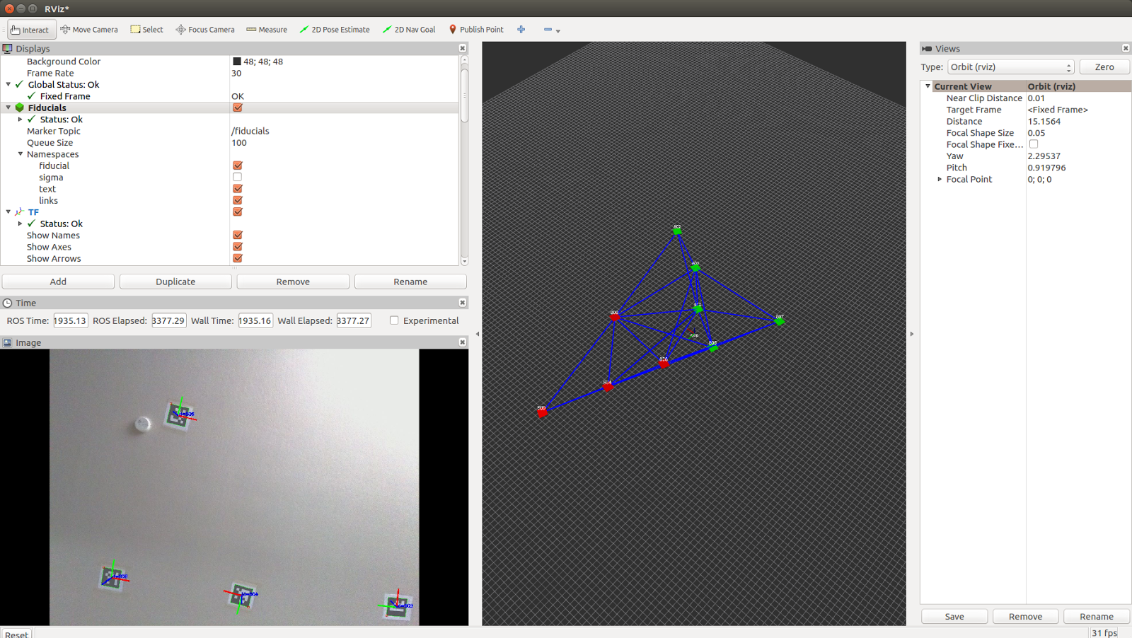
roslaunch magni_viz view_nav.launch
This will produce a display as shown below. The bottom left pane shows the current camera view. This is useful for determining if the fiducial density is sufficient. The right-hand pane shows the map of fiducials as it is being built. Red cubes represent fiducials that are currently in view of the camera. Green cubes represent fiducials that are in the map, but not currently in the view of the camera. The blue lines show connected pairs of fiducials that have been observed in the camera view at the same time. The more blue lines there are between fiducials, the more robust the map will be.
Using The Global Map For Magni Navigation
Once you have created a global map for your robot accessible area you can then begin to navigate the Magni by using our original navigation mode.
The existing navigation mode (originally released in 2018) can be started just like map creation. This mode will add in new fiducials to the global map as it sees them and allow navigation at the same time.
roslaunch magni_demos simple_navigation.launch
We have been developing a more precise mode suitable for use on flat floors which we hope to release in early 2020. Once this is available we can start the navigation in a mode that only reads from our global map. This can be done repeatedly and even on other Magni robots that have this map file in the same location – which is ~/.ros/slam/map.txt.
roslaunch magni_demos simple_navigation_flat.launch
Using Navigation Commands To Move Magni
Once a navigation stack is running such as at this point we are able to tell Magni to move to a specific X,Y location and then rotate to a specific angular rotation. Magni will be running move_basic from the above roslaunch and so will be ready to accept commands to move to a given X,Y with a given rotation by sending MoveBaseGoal messages to ROS topic /move_base/goal.
Once a move_basic goal is sent move_basic will try to complete the movement and then return status on another topic for success/fail of the movement.
There is a demonstration python script to help users get started with sending robot positions to the move_basic action server. The app can get the robot to move along patterns setup in tables and may be found on THIS_PAGE