↑top
GPIO Lines In Use And Using Them For Your Own Needs
You must remove the battery cables when working on the boards because live battery voltage is on the board and on P702! Powering off the Magni will not prevent the live voltages!
There are many GPIO lines used for features of Magni that could also be re purposed for your own needs if that is required. The most logical way to use these lines is use a custom 50-pin ribbon cable that would normally go to our Sonar board on jack P702. You could then make a custom board to attach to lines of this connector as long as you make sure the lines will not be used by the Magni software.
The first 40 pins of P702, the 50 pin Sensor Board connector, are the same pin numbers as the Raspberry Pi 40 pins on P701. Pins shown in the tables below are therefore used on both of the large dual row connectors on the Motor Controller Board.
This page explains the GPIO line usage and how to disable features if you need to use the lines yourself.
GPIO lines not listed on this page are available for your own usage without any configuration changes to the Magni
GPIO Lines Required For Control Of The Robot
There are a few lines that if you are using our robot you must let our system use these lines even for the base product with no options like sonar board and so on. The lines in the table below are reserved for usage by our ROS motor_node to control the main board called the MCB board from the Host CPU (Usually Raspberry Pi).
| GPIO | RasPi Pin | P702 Pin | Default Magni Usage |
|---|---|---|---|
| 2 | 3 | 3 | I2C bus Data line (SDA) |
| 3 | 5 | 5 | I2C bus Clock line (SCL) |
| 14 | 8 | 8 | Transmit serial port pin from host to MCB (SIN led on MCB) |
| 15 | 10 | 10 | Receive serial port pin from MCB to host (SOUT led on MCB) |
GPIO Lines Used For Status LED and Switches
There are two GPIO inputs used for switches and two GPIO outputs used to drive LEDs on the Sonar Board. The two GPIO input lines intended to be used for switches on the Sonar board appear on two 3-pin jacks on the MCB for P704 and P705.
If you do not use the Sonar board OR are willing to sacrifice the features for two of the inputs and two of the outputs for leds for Magni Silver and Magni Gold here is the information required.
You can use P704 and P705 jacks which have one GPIO each after disabling the usage of these by Magni because by default they are for two switches on the Sonar board. Normally those 2 jacks and their Magni usage AND two other GPIO pins used to drive LEDs that exist on the Magni ‘Sonar Board’ are controlled by Magni. The first 40 pins of both jacks are identical but notice carefully each pin one as they are not aligned and it is tricky because the Raspberry Pi is plugged in to P701 making the pin numbering a bit ‘upside down’.
| GPIO | RasPi Pin | P702 Pin | Default Magni Usage |
|---|---|---|---|
| 5 | 29 | 29 | WiFi Status LED on the sonar board and rev 5.2 MCB |
| 25 | 22 | 22 | Status LED on the sonar board |
| 6 | 31 | 31 | Goes to P704 pin 2. Does a shutdown when grounded. This goes to a pushbutton on Sonar Board near 50 pin connector. |
| 13 | 33 | 33 | Goes to P705 pin 2. Used for PiFi and goes to a pushbutton on the Sonar Board |
Always remove the battery cables so no live voltage is present on P702!
The serial transmit and receive are always required by the motor_node and we have no mechanism to disable their usage except disconnect the MCB and then do not let the motor_node run is only of use for non-Magni users of our image.
To use these as GPIO you must edit two files as root Edit /etc/pifi/pifi.conf:
-
Change the line for status_led to be set to None like this
status_led: None -
Change the line for button_device_name to None like this
button_device_name: None
Edit /boot/config.txt (be very careful to ONLY change the one line) Remove the one line shown below and save the file
dtoverlay=ubiquity-led-buttons
Pifi should still work but you would not get WiFi LED indication or be able to use the button that is used with PiFi
To be able to drive the 2 LEDs on the sonar board yourself or just use GPIO 5 and 25 when there is no Sonar Board you will need to edit /boot/config.txt and comment out ‘dtoverlay=ubiquity-leds-buttons’
Doing both of the above changes frees up the 4 GPIO lines for your purposes and you should also configure them as your application requires.
GPIO lines 6 and 13 go to some 3-pin jacks, P704 and P705, where pin 1 is ground and short to pin 2 to ‘close’ or make that GPIO line low.
Pin 3 of both jacks is 3.3 volts on the Raspberry Pi if you need that for your sensors keep the current usage low. Do not short this pin to ground! Starting with MCB rev 5.2 there is an onboard 3.3V regulator so the MCB can power some of the 3.3V chips like serial line buffers and the OLED display without use of a Raspberry Pi supply. The onboard 3.3V regulator does not connect to the pin 3 lines of either jack.
Pin 2 of P704 and P705 goes directly to Raspberry PI GPIO so do NOT connect to 5V because it is for 3.3 volt maximum input.
GPIO Lines Used For The Sonar Board
There are many other GPIO lines used for the sensor board. If the sensor board is not in use you may ensure the configuration is not trying to use the Sonar board and then the GPIO lines would be available for your own use.
To use the lines you must disable the sensors. As root you will need to edit robot.yaml file.
sudo nano /etc/ubiquity/robot.yaml
In the robot.yaml file be sure the sonars: line is set to None as below and if you see something other than None you need to comment out that line as shown using pound sign. Just to be clear: IF you set sonars: to None the sonar board will not be used although the leds and buttons explained earlier in this page may still be of value to you.
# Robot Configuration
sonars: None
# sonars: ‘pi_sonar_v1’
The Sonar Board uses many GPIO lines that are shown the table below and again the pin numbers on P701 and P702 are the same for the first 40 pins.
| GPIO | Pin | Comment |
|---|---|---|
| 20 | 38 | Sonar 0 Trigger |
| 21 | 40 | Sonar 0 Echo |
| 12 | 32 | Sonar 1 Trigger |
| 16 | 36 | Sonar 1 Echo |
| 23 | 16 | Sonar 2 Trigger |
| 24 | 18 | Sonar 2 Echo |
| 27 | 13 | Sonar 3 Trigger |
| 22 | 15 | Sonar 3 Echo |
| 19 | 35 | Sonar 4 Trigger |
| 26 | 37 | Sonar 4 Echo |
## GPIO Lines With Planned Future Usage
Here are 5 more GPIO lines that are not in use at this time that we have plans for in a future IO board. Because the board does not exist today and because GPIO lines are in such high demand we will list them here. When we used these in the future there will be specific lines in a config file to enable usage of them that will be off by default so these lines can be considered usable at this time.
| GPIO | Pin | Function |
|---|---|---|
| 4 | 7 | GPIO04 GPCLK0 |
| 17 | 11 | GPIO17 |
| 10 | 19 | GPIO10 SPI0_MOSI |
| 9 | 21 | GPIO09 SPI0_MISO |
| 11 | 23 | GPIO11 SPI0_CLK |
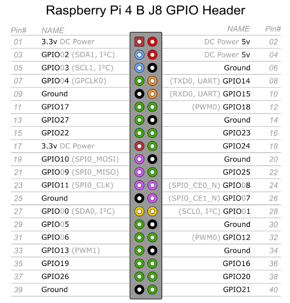
## Raspberry Pi Main 40 pin Connector Pinout
Here is a full pinout of the Raspberry Pi 40 pin connector which may come in handy for a reference. There are plenty of these on the web but it is important to note there are two numberings of the GPIO port numbers. This drawing below agrees with the numbering scheme we use in our documents.